The increa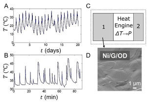 sing demand of clean energy has inspired substantial effort in developing renewable energy harvesting technologies. Heat is a pervasive energy source in nature and industrial activities. Thermal energy in the form of spatial temperature gradient can be readily harvested by thermoelectric devices. On the contrary, transient temperature variations in the environment are another potential source of thermal energy that have been relatively unexplored. Their small spatial and temporal gradients represent an austere challenge for conventional techniques, such as pyroelectric, thermoelectric, and thermophotovoltaic. In recent works, this challenge has been overcome by converting temporal variation into spatial temperature gradients such that conversion to electrical energy can be appreciable.
Inspired by this strategy, the concept of a thermal resonator has been developed, and demonstrated experimentally as a sustainable energy harvesting device capable of converting a broad band of temperature waveforms into electricity.[1-6] Physical models have been constructed and investigated, providing a systematic consideration of optimal materials and device design. Thermal resonators are shown to be a durable power source in a variety of environments, and can be used to power wireless sensor nodes.
Various forms of temperature variations have been measured, such as diurnal cycles in an outdoor environment (Fig. A) and duty cycles of a laptop (Fig. B). To convert them into spatial gradient, we have conceived a generic design of a thermal resonator (Fig. C), which consists of a heat engine (usually a thermoelectric module) sandwiched between 2 blocks of materials, known as thermal masses.[1, 5] Thermal mass 2 is made of a material with high thermal conductivity and low heat capacity, typically in the form of metallic fins. Its role is to maximize heat exchange with the environment. In contrast, the function of thermal mass 1 is to absorb and store thermal energy during the hot part of the temperature cycle, and then to release this heat in the cold part of the cycle (Fig. D).
References:
[1] Cottrill, A. L.; Zhang, G.; Liu, A. T.; Bakytbekov, A.; Silmore, K. S.; Koman, V. B.; Shamim, A.; Strano, M. S., Appl. Energy 2019, 235, 1514.
[2] Zhang, G.; Cottrill, A. L.; Koman, V. B.; Liu, A. T.; Mahajan, S. G.; Piephoff, D. E.; Strano, M. S., Appl. Energy 2020, 280, 115881.
[3] Liao, X. Z.; Liu, Y. X.; Ren, J. H.; Guan, L. P.; Sang, X. H.; Wang, B. W.; Zhang, H.; Wang, Q. W.; Ma, T., Energy 2020, 202, 117724.
[4] Bakytbekov, A.; Nguyen, T. Q.; Li, W.; Lee Cottrill, A.; Zhang, G.; Strano, M. S.; Salama, K. N.; Shamim, A., Energy Science & Engineering 2020, 10.1002/ese3.784
[5] Cottrill, A. L.; Liu, A. T.; Kunai, Y.; Koman, V. B.; Kaplan, A.; Mahajan, S. G.; Liu, P. W.; Toland, A. R.; Strano, M. S., Nat. Commun. 2018, 9, 664.
[6] Wang, S.; Cottrill, A. L.; Kunai, Y.; Toland, A. R.; Liu, P. W.; Wang, W. J.; Strano, M. S., Phys. Chem. Chem. Phys. 2017, 19, 13172.